Premium content
Access to this content requires a subscription. You must be a premium user to view this content.

Would you like to see your presentation here, made available to a global audience of researchers?
Add your own presentation or have us affordably record your next conference.
Soft magnetic composite (SMC) material is a relative new soft magnetic material, which has many advantages over traditional silicon sheets, however it has many disadvantages as well. For the better utilization of SMC material in developing electrical machines, some design guidelines should be followed, e.g., 3D magnetic flux path, high frequency operation, and permanent magnet excitation 1. There are many electrical machines with SMC cores had been developed in the past decades. Based on global ring winding and 3D magnetic flux path, permanent magnet claw pole machine (PMCPM) has shown its high torque ability compared with other electrical machines 2. For the most PMCPM, three same single phase PMCPM modules are required with shifting 120 degrees electrically each other to form three phase operation, and each one phase module has its own PM rotor thus the PM utilization is very low 3. In this paper, for improving the PM rotor utilization a novel axial radial flux permanent magnet claw pole machine ARPMCPM is proposed and designed where there stators share one PM rotor. For the performance prediction, 3D finite element method (FEM) is used.
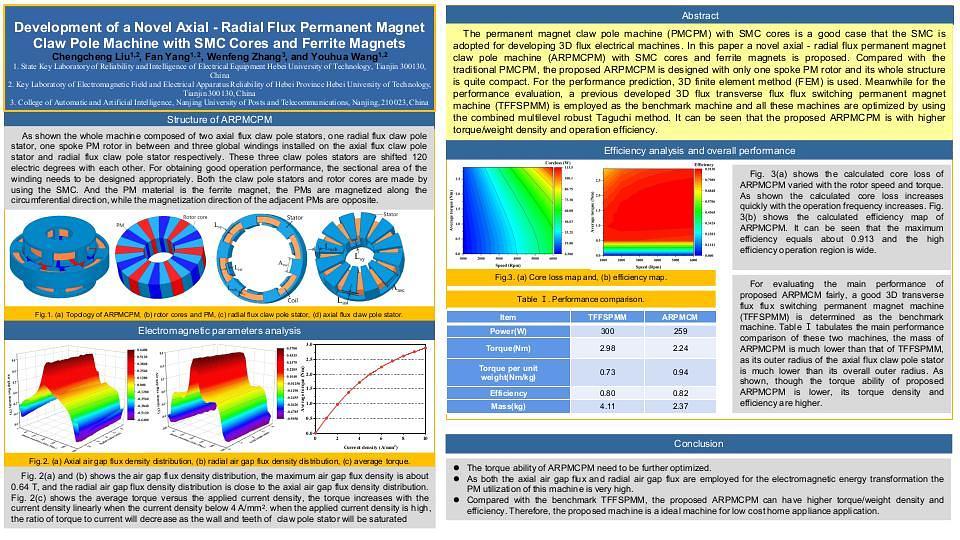
Fig. 1 shows the main magnetic structure of the ARPMCPM. As shown, one radial flux claw pole stator and two axial flux claw pole stators are required, the global ring winding is adopted, and spoke PM configuration is adopted for the PM rotor. To form three phase operation, these three claw pole stators are shifted 120 degrees electrically to each other and the winding section area needs to be designed reasonably. Fig. 2 shows no load magnetic field distribution, parameters and main performance of ARPMCPM based on 3D FEM. Fig. 2(b) shows the no load PM flux linkage of winding A, B and C. As shown, A phase PM flux linkage higher than the other PM flux linkages as winding A is located on the radial flux claw pole stator. Fig. 2(c) shows the induced voltages. Fig. 2(d) shows the torque waveform under the current density of 6 A/mm2. Fig. 2(e) and (f) are the core loss and efficiency map. More details and design methods for the ARPMCPM will be presented in the full submission.
