Premium content
Access to this content requires a subscription. You must be a premium user to view this content.

Would you like to see your presentation here, made available to a global audience of researchers?
Add your own presentation or have us affordably record your next conference.
Skyrmions are of great interest in spintronic devices because their small size and the high-speed motion when driven by a current or a spin-wave (SW). Skyrmion motion
along a narrow track is important for racetrack-type spintronic devices, since a skyrmion moving along the propagation direction of an injected electrical or SW current (forward) is the
means by which data are moving1. To design the devices, knowing how to adjust the skyrmion motion becomes important.
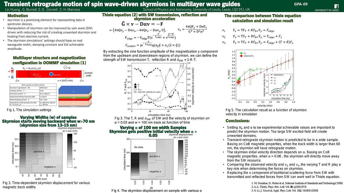
We carried out simulations of SW driven skyrmion motion using OOMMF 2, with fixed parameters D = 1.5 mJ/m2, MS = 1004 kA/m, A = 3.6 pJ/m, and Ku = 1 MJ/m3. We found that for tracks narrower than 50 nm the skyrmion always moves forwards. For wider tracks, the skyrmion will initially move both backward and close to the track edge, before moving forward at longer times once the track edge is reached, as shown in Fig 1. We attribute this to an additional repulsive force on the skyrmion from the track edge. For samples with Gilbert damping
constant α > 0.06, the skyrmion will move forward without retrograde motion.
The Thiele equation is a widely-used way to analyse skyrmion motion. The SW driving force on a skyrmion is usually the SW scattering force 3, but the strength of the scattering and the
energy change associated with changes in skyrmion size owing to absorbed SWs are hard to extract from magnetization data. Thus, we use the SW transmission T and reflection
coefficients R to make an estimate of the forces involved. We can obtain T from the ratio of the SW amplitude downstream of the skyrmion and without skyrmion at same position.
Similarly, we obtain R from the difference between magnetization data upstream of the skyrmion and without skyrmion.
As an example, we consider the data from a simulation with track width w = 100 nm and α = 0.03. By Analysing T and R, the decrease in T after ~30 ns, shown in Fig.2, will reduce the
effort that leads to the skyrmion moving backward. Meanwhile the increasing force from the sample edge also helps the skyrmion overcome the Spin-Ttansfer Torque between transmitted
SW and skyrmion4, allowing it to move forwards.
References
1. Sampaio, J., Cros, V. et al. Nature Nanotech 8, 839–844 (2013)
2. Donahue, M., Porter D. et al, National Institute of Standards and Technology(1999)
3. Zhang, X. et al New J. Phys. 19, 065001 (2017)
4. Yan, X., S. Wang et al. Phys. Rev. Lett. 107, 177207 (2011)

The snapshots of w = 40 nm, 90 nm tracks

Time-dependent SW T, R, A and skyrmion acceleration data
