Premium content
Access to this content requires a subscription. You must be a premium user to view this content.

Would you like to see your presentation here, made available to a global audience of researchers?
Add your own presentation or have us affordably record your next conference.
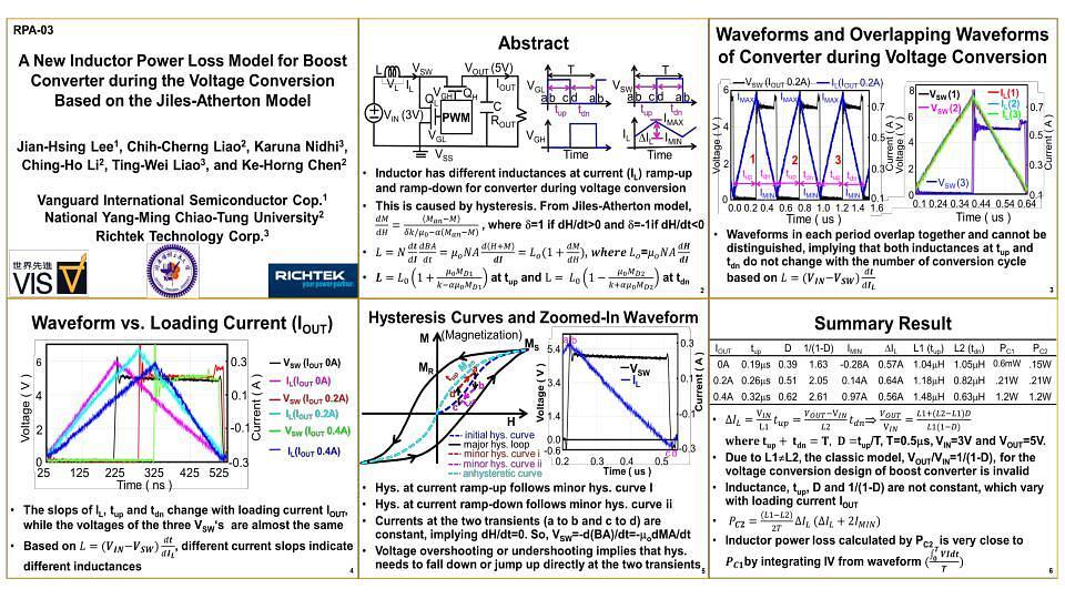
Abstract—The Jiles-Atherton (J-A) model 1 predicts that an inductor has different inductances at the current ramp-up time (ton) and ramp-down time (toff). For the first time, this phenomenon is observed at the boost converter (Fig. 1) during the voltage converter (Fig. 2) and a simple equation to depict it is derived. Moreover, the methodology to calculate the inductor power loss from the voltage conversion data directly for a boost converter is presented.
I. Model and Experiment Result
From Fraday law, the inductance is
L=NdBA/(dt(dI/dt))=uNA d(H+M)/dI= Lo(1+dM/dH) (1)
From the J-A model, the differential of total magnetization M is
dM/dH=(Man-M)/((dk/m)-a(Man-M)) (2)
where d=1 if dH/dt>0 and d=-1 if dH/dt < 0.
From the experiment result in Figs. 3-5, Man-M can be approximated to a constant MD since the voltage almost keeps constant at each ton or toff based on L=V/(dI/dt). So, the inductance at ton is given by
L= Lo(1+mMD/(k-aMD)=L1 (3)
The inductance at toff is given by
L= Lo(1-mMD/(k+aMD)=L2 (4)
Figs. 3-5 show the voltage and current waveforms of the boost converter during the voltage conversion for the output currents (IOUT in Fig. 1) 0A, 0.2A and 0.4A. However, the three different IOUT waveforms have different ton and toff due to different slops by aligning their base current level with the current waveform for IOUT=0A as shown in Fig. 6. It proves that an inductor has the different inductances at ton and toff and L1 at ton is larger than Lo and L2 at toff is smaller than Lo. This is caused by the hysteresis effect as shown in Fig. 7 since it follows the initial hysteresis loop, minor hysteresis curves i and ii for Lo, L1 and L2. Integrating the powers at ton and toff and divided by the period T, the inductor power loss for boost converter during the voltage conversion is Ploss=(L1-L2)dIL(dIL+2IMIN)/2T (5)
where dIL is the peak-to-peak inductor current, IMIN is the minimum inductor current in Fig. 2.
Table-I shows the input power, measured inductor power loss based on Figs. 3-5 and calculated inductor power loss based on Eq. (5). The calculated power loss is very close to the measured power loss, verifying Eq. (5) valid to calculate the inductor power loss from the electrical voltage conversion data directly.
References:
1 D. C. Jiles and D. L. Atheron, “Theory of Ferromagnetic Hysteresis,” J. of Magnetism and Magnetic Materials, pp. 48-60, 1986.