Premium content
Access to this content requires a subscription. You must be a premium user to view this content.

Would you like to see your presentation here, made available to a global audience of researchers?
Add your own presentation or have us affordably record your next conference.
In-wheel motor is regarded as the most promising drive system of next generation electric vehicles in merit of high transmission efficiency, flexible control and compact
structure 1. Since the in-wheel motor often operates under different conditions and possesses multiple external heat sources, electromagnetism-thermal analysis is essential during the
motor design stage 2. Generally, the current electromagnetism-thermal analysis is based on finite element analysis (FEA), the large time-consumptions of this method brings challenges to
the design of this kind of motor 3. Therefore, a rapid design method of in-wheel motor based on a common-node magneto-thermal bidirectional coupling network (CMTBCN) model is
proposed in this paper. In the CMTBCN model, some nodes of the motor are used as common nodes of the equivalent magnetic network (EMN) model and the equivalent thermal network
(ETN) model to avoid repeated modeling. Then the effect of temperature on the coercivity and permeability of permanent magnets is considered in EMN, the losses calculated by EMN at
initial temperature are used as the heat sources of ETN to calculate the new temperature. The temperature of each component of the motor and the electromagnetic performance under
different working conditions can be obtained more accurately by using the bidirectional coupling method. Finally, an in-wheel motor is designed and optimized based on CMTBCN model.
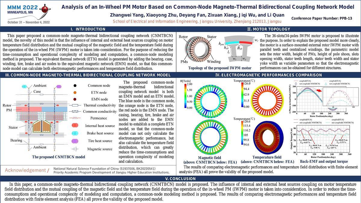
Fig. 1 (a) shows the 3D structure and parametric model of the in-wheel motor. Fig. 1 (b) shows the proposed common-node magneto-thermal bidirectional coupling network model. Fig. 2
(a) compared the airgap flux density and its harmonic analysis obtained by CMTBCN and FEA. Fig. 2 (b) compared the A-phase no-load flux linkage and back-EMF obtained by
CMTBCN and FEA at -20 and 100 degrees Celsius. Fig. 2 (c) shows the static temperature distribution of the in-wheel motor under the rated load obtained by FEA. Fig. 2 (d) shows the
prototype of stator and rotor of the proposed in-wheel motor.
More detailed analysis and experimental verification will be presented in the full paper.
References:
1 P. Liang, F. Chai and Y. Yu, IEEE Transactions on Industrial Electronics, vol. 66, no. 2, pp. 1162-1171, Feb. 2019.
2 X. Chen and G. Li, 2020 13th International Conference on Intelligent Computation Technology and Automation (ICICTA), 2020, pp. 683-686.
3 X. Li, F. Shen and S. Yu, IEEE Transactions on Industrial Electronics, vol. 68, no. 8, pp. 6560-6573, Aug. 2021.


